
Group Safety Standard: IEC 60204-1: 2016 | USA
Table of contents
1. Positioning of IEC 60204-1
2. Voltage range and operating environment
3. Incoming supply conductor terminations
4. Protection against electric shock
5. Protection of equipment
6. Equipotential bonding
7. Control circuits and control functions
8. Operator interface
9. Location, mounting, and enclosure of control devices
10. Selection of cables
11. Wiring practices
12. Warning signs and markings
13. Technical documentation
1. Positioning of IEC 60204-1
ISO 12100 states that IEC 60204-1 (Safety of machinery - Electrical equipment of machines - Part 1: General requirements) should be referred to for measures against electrical hazards identified in the risk assessment. IEC 60204-1 is an important standard in the field of machine safety that forms the basis for ensuring the safety of electrical equipment.
The three purposes of this standard are as follows.
Safety of persons and property (including equipment, devices and components)
Consistency of control response
Ease of operation and maintenance
The standard is intended not only to prevent persons from electric shock, but also to prevent electrical fires and other damage to a machine itself as well as to devices used, workpieces, and other components. In addition, the standard is intended to ensure “intended control response”, “operability based on the ergonomic principles”, and “ease of maintenance”. The requirements to achieve these purposes are provided.
IEC 60204-1 applies to:
electrical, electronic and programmable electronic equipment and systems to machines not portable by hand while working, including a group of machines working together in a co-ordinated manner
the equipment commencing at the point of connection of the supply to the electrical equipment of the machine
electrical equipment or parts of the electrical equipment operating with nominal supply voltages not exceeding 1,000 V for alternating current (AC) and not exceeding 1,500 V for direct current (DC), and nominal supply frequencies not exceeding 200 Hz
This standard does not specify additional and special requirements that can apply to the electrical equipment of machines that, for example:
are intended for use in open air (i.e. outside buildings or other protective structures);
use, process, or produce potentially explosive material (for example paint or saw-dust);
are intended for use in potentially explosive and/or flammable atmospheres;
have special risks when producing or using certain materials;
are intended for use in mines;
are sewing machines, units, and systems (which are covered by IEC 60204-31);
are hoisting machines (which are covered by IEC 60204-32);
are semiconductor fabrication equipment (which are covered by IEC 60204-33)
Figure 1 shows the sections relevant to this standard.
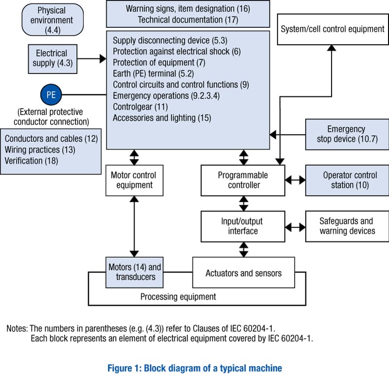
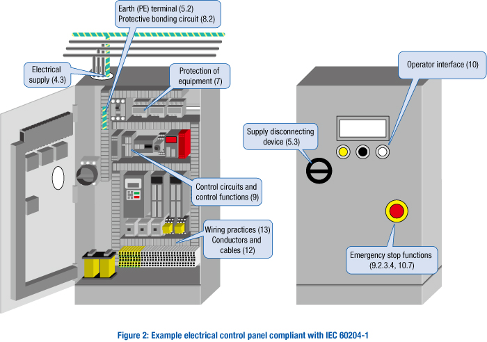
Figure 2 shows elements from Figure 1 applied to an electrical control panel.
2. Voltage range and operating environment
First, electrical components and devices shall:
be suitable for the intended use; and
conform to relevant IEC standards where such exist; and
be applied in accordance with the supplier’s instructions.
In addition to satisfying the above, the electrical equipment must operate correctly under the following conditions.
Voltage range (4.3)
The electrical equipment must operate correctly under any of the following electrical supply conditions.
AC supplies (4.3.2)
Voltage
Steady-state voltage: 0.9 to 1.1 of nominal voltage
Frequency
0.99 to 1.01 of nominal frequency (continuously) or 0.98 to 1.02 (short time)
Voltage interruption
Supply interrupted or at zero voltage for not more than 3 ms at any random time in the supply cycle with more than 1 s between successive interruptions.
DC supplies (4.3.3)
Voltage
0.85 to 1.15 of nominal voltage
0.7 to 1.2 of nominal voltage in the case of battery-operated vehicles
Voltage interruption
Not exceeding 5 ms
From converting equipment
Voltage
0.9 to 1.1 of nominal voltage
Voltage interruption
Not exceeding 20 ms with more than 1 s between successive interruptions
Ambient air temperature (4.4.3)
The minimum requirement for all electrical equipment is correct operation in ambient air temperatures between 5 °C and 40 °C outside of enclosures.
Humidity (4.4.4)
The electrical equipment shall be capable of operating correctly when the relative humidity does not exceed 50% at a maximum temperature of 40 °C. Higher relative humidities are permitted at lower temperatures (for example, 90% at 20 °C).
Altitude (4.4.5)
The electrical equipment shall be capable of operating correctly at altitudes up to 1,000 m above sea level.
For equipment to be used at higher altitudes, it is necessary to take changes in parameters into account, such as the reduction of:
the dielectric strength;
the switching capability of the devices; and
the cooling effect of the air.
Transportation and storage (4.5)
The equipment shall be designed to withstand, or suitable precautions shall be taken to protect against, the effects of transportation and storage temperatures between –25°C and 55°C, (up to 70°C for short periods not exceeding 24 hours).
3. Incoming supply conductor terminations
To connect the input supply conductors with the electrical equipment of the machine, such as a control panel, the supply conductors are connected directly to the supply disconnecting device or via a plug (socket outlet, etc.). At that time, it is recommended that the electrical equipment is connected to a single supply whenever possible.
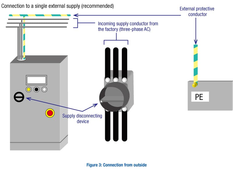
Requirements for supply disconnecting devices (primary applicable standard: IEC 60947-3)
A supply disconnecting device shall be provided for each incoming supply to a machine(s) and for each on-board power supply. (5.3.1)
Supply disconnecting devices serve to disconnect the control panel from the factory’s electrical supply, for example when a maintenance person opens the control panel to carry out some kind of maintenance work. This allows maintenance personnel to carry out maintenance without being exposed to electrical hazards. Since the supply disconnecting devices have such an important role, they shall meet all of the following requirements:
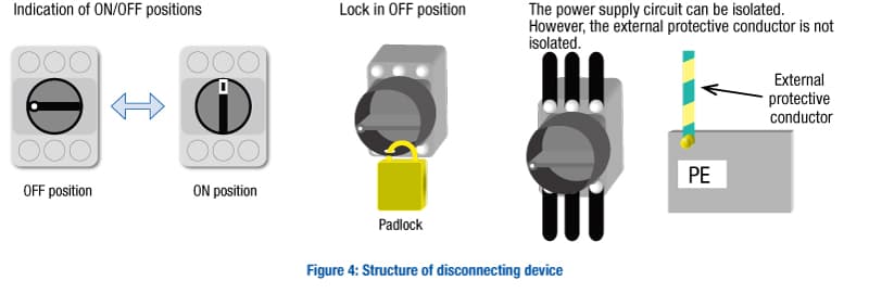
have one OFF (isolated) and one ON (closed) position marked with “○” and “|” symbols.
have a visible contact gap or a position indicator which cannot indicate OFF (isolated) until all contacts are actually open and the requirements for the isolating function have been satisfied.
have an operating means (for example, a handle), which shall be external to the enclosure of the electrical equipment. Where the external operating means is not intended for emergency operations, it is recommended that it be colored black or gray. Where intended for emergency use, the color red shall be used on a yellow background.
be provided with a means permitting it to be locked in the OFF (isolated) position (for example by padlocks). When so locked, remote as well as local closing shall be prevented;
disconnect all live conductors of its power supply circuit;
have a breaking capacity sufficient to interrupt the current of the largest motor when stalled together with the sum of the normal running currents of all other motors and other loads.
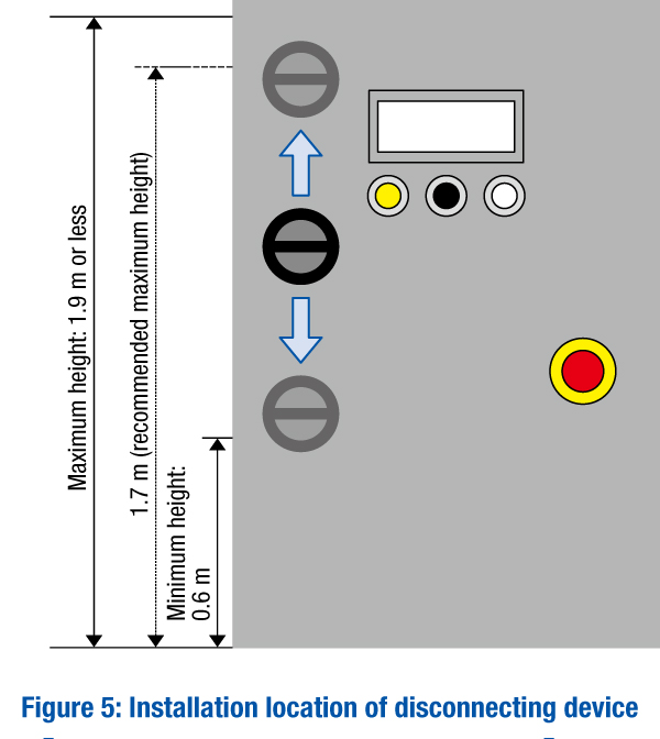
The operating means of the supply disconnecting device shall be easily accessible and located between 0.6 m and 1.9 m above the servicing level. An upper limit of 1.7 m is recommended.
Excepted circuits:
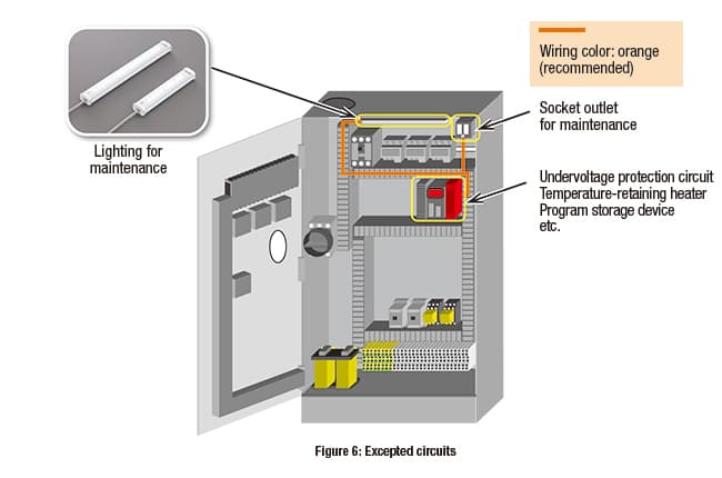
Excepted circuits are circuits that do not need to be disconnected by the supply disconnecting device to ensure safety in abnormal situations or during maintenance. The following can be considered as excepted circuits:
lighting circuits for lighting needed during maintenance or repair;
socket outlets for the exclusive connection of repair or maintenance tools and equipment (for example, hand drills and test equipment);
undervoltage protection circuits that are only provided for automatic tripping in the event of supply failure;
circuits supplying equipment that should normally remain energized for correct operation (for example, temperature-controlled measuring devices and heaters).
It is recommended, however, that such circuits be provided with their own disconnecting device.
4. Protection against electric shock
The electrical equipment shall provide measures of protection against electric shock.
There are two types of electric shock, defined as follows.
Direct contact (3.1.15): contact of persons or livestock with live parts (*1)
Indirect contact (3.1.34): contact of persons or livestock with exposed conductive parts (*2) which have become live under fault conditions
*1) A live part is defined in IEC 60204-1 as a “conductor or conductive part intended to be energized in normal use” (3.1.38).
*2) Conductive parts of electrical equipment, accessible to persons, which can be touched and which are not live under normal operating conditions, but which can become live under fault conditions.
Protective measures against the electric shocks described above are defined as follows.
Basic protection (3.1.4): protection against electric shock (i.e. electric shock due to direct contact) under fault-free (i.e. free from insulation faults) conditions
(Insulation) fault protection (3.1.31): protection against electric shock (i.e. electric shock due to indirect contact) under single-fault conditions
These protection measures are categorized in IEC 60204-1 as shown in Table 1 below.
| Basic protection(6.2) | Protection by enclosures(6.2.2) | |
| Protection by insulation of live parts(6.2.3) | ||
| Protection against residual voltages(6.2.4) | ||
| Protection by barriers(6.2.5) | ||
| Protection by placing out of reach or protection by obstacles(6.2.6) | ||
| (Insulation) fault protection(6.3) | Prevention of the occurrence of a touch voltage(6.3.2) | Protection by provision of class II equipment or by equivalent insulation(6.3.2.2) |
| Protection by electrical separation(6.3.2.3) | ||
| Protection by automatic disconnection of supply(6.3.3) | a)TN earthing systems | |
| b)TT earthing systems | ||
| c)IT earthing systems | ||
| Protection by the use of PELV(6.4) | ||
For the purpose of basic protection, measures such as covering live parts with an enclosure or maintaining adequate distance are taken to prevent electric shock to workers by avoiding direct contact with live parts under normal operating conditions.
For the purpose of (insulation) fault protection, measures are taken to prevent electric shock to workers caused by exposed conductive parts that may become live in the event of an insulation fault. Either of the following measures is used: preventing exposed conductive parts from becoming energized, in the first place; and automatically disconnecting the supply by means of an overcurrent protective device or a residual current device when exposed conductive parts become live.
For protection by the use of PELV (protective extra-low voltage), measures are taken to protect persons against electric shock from indirect contact and limited-area direct contact.
5. Protection of equipment
This refers to measures for preventing damage to equipment, as well as electrical fires, due to overcurrent or temperature rise. Typical measures include protection of equipment by using an overcurrent protective device.
Overcurrent protection shall be provided where the current in any circuit can exceed either the rating of any component or the current carrying capacity of the conductors, whichever is the lesser value (7.2.1).
An overcurrent protective device is required for the following.
Supply conductors (7.2.2)
Power circuits (7.2.3)
Control circuits (7.2.4)
Socket outlets and their associated conductors (7.2.5)
Lighting circuits (7.2.6)
Transformers (7.2.7)
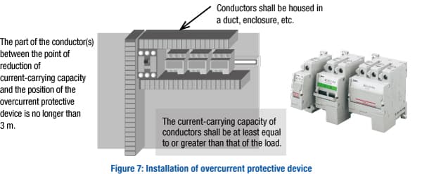
In addition, the following conditions are related to the installation of overcurrent protective devices. Unless all of the following conditions are satisfied, an overcurrent protective device shall be installed:
the current carrying capacity of the conductors is at least equal to that of the load.
the part of the conductor(s) between the point of reduction of current-carrying capacity and the position of the overcurrent protective device is no longer than 3 m;
the conductors are installed in such a manner as to reduce the possibility of a short circuit, for example, protected by an enclosure or duct.
6. Equipotential bonding
Equipotential bonding is “provision of electric connections between conductive parts, intended to achieve equipotentiality (3.1.26)”, which includes protective bonding and functional bonding.
Protective bonding is “equipotential bonding for protection against electric shock (3.1.49)”, while functional bonding is “equipotential bonding necessary for proper functioning of electrical equipment (3.1.32)”.
As stated in the standard, “Protective bonding is a basic provision for fault protection to enable protection of persons against electric shock.”. Protective bonding plays an especially important role in the event of an insulation fault.
A protective bonding circuit consists of the interconnection of the following (8.2.1):
terminal for connection of the external protective conductor
the protective conductors* in the equipment of the machine
the conductive structural parts and exposed conductive parts of the electrical equipment
conductive structural parts of the machine
* A conductor providing a primary fault current path from the exposed conductive parts of the electrical equipment to a PE terminal.
By interconnecting these, persons are protected against electric shock caused by earth-fault currents or leakage currents in the event of an insulation fault.
Where an earth fault occurs, a large current may flow through the protective conductor. Therefore, the protective conductor must be able to withstand thermal stress due to the large current. In addition, it is also necessary to prevent mechanical damage to the protective conductor in order to ensure the continuity of the protective bonding circuit.
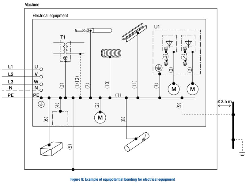
| Protective bonding circuit | |
| (1) | Interconnection of protective conductor(s) and the PE terminal |
| (2) | Connection of the exposed conductive parts |
| (3) | Protective conductor connected to an electrical equipment mounting plate used as a protective conductor |
| (4) | Connection of conductive structural parts of the electrical equipment |
| (5) | Conductive structural parts of the machine |
| Parts connected to the protective bonding circuit which are not to be used as protective conductor | |
| (6) | Metal ducts of flexible or rigid construction |
| (7) | Metallic cable sheaths or armoring |
| (8) | Metallic pipes containing flammable materials |
| (9) | Extraneous-conductive-parts, if earthed independently from the power supply of the machine and liable to introduce a potential, generally the earth potential, e.g. metallic pipes, fences, ladders, handrails |
| (10) | Flexible or pliable (can be shaped manually) metal conduits |
| (11) | Protective bonding of support wires, cable trays, and cable ladders |
| Connections to the protective bonding circuit for functional reasons | |
| (12) | Functional bonding |
| Legend to reference designations | |
| T1 | Auxiliary transformer |
| U1 | Mounting plate of electrical equipment |
Each protective conductor connection point shall be marked with one of the following:


7. Control circuits and control functions
As stated in the purposes of IEC 60204-1, ensuring the consistency of control response is important for safety. Therefore, the following requirements apply:
supply voltage of control circuits
stop and operation as the control functions
Where control circuits are supplied from an AC source, transformers shall be used to separate the power supply from the control supply.
This transformer shall have separate windings (compound winding). (9.1.1)
In addition, the nominal voltage of control circuits should preferably not exceed the following: (9.1.2)
AC control circuits
230 V (for circuits with 50 Hz nominal frequency)
277 V (for circuits with 60 Hz nominal frequency)
DC control circuits
Nominal voltage of 220 V
As mentioned in ’5. Protection of equipment’, control circuits shall be provided with overcurrent protective devices. (9.1.3)
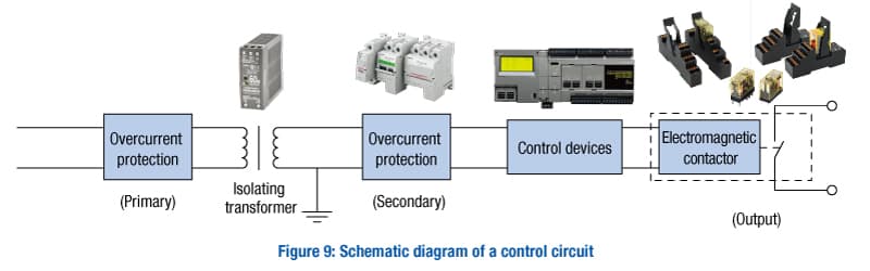
The following are typical control functions.
Start (9.2.3.2)
Start functions of the machine shall operate by energizing the relevant circuit. The start of an operation shall be possible only when all relevant safety functions and/or protective measures are in place and are operational.
Stop (9.2.3.3)
Stop functions shall override start functions. Stop functions are classified into the following three stop categories, which shall be selected in accordance with the risk assessment and/or the functional requirements of the machine.
| Stop category | Control name | ISO 14118 (JIS B 9714) | Description of stop state |
| 0 | Uncontrolled stop | Stop state | Stopping by immediate removal of power to the machine actuators |
| 1 | Controlled stop | A controlled stop with power available to the machine actuators to achieve the stop, and then removal of power when the stop is achieved | |
| 2 | At-rest state | Controlled stop with power remaining available to the machine actuators even after the stop is completed |
Operating modes (9.2.3.5)
Each machine can have one or more operating modes (for example, manual, automatic, setting, and maintenance modes) determined by the type of machine and its application.
Where different operating modes require different protective measures and have a different impact on safety, the electrical equipment shall be fitted with a mode selector which can be locked in each position (for example, a key-operated switch). Each position of the selector shall be clearly identifiable and shall correspond to a single operating or control mode. The selector may be replaced by another selection method which restricts the use of certain functions of the machinery to certain categories of operator (for example, an access code).
Mode selection by itself shall not initiate machine operation.
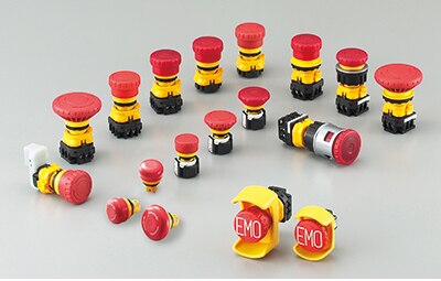
Emergency stop (9.2.3.4.2)
An emergency stop shall function as stop category 0 or as stop category 1.
An emergency stop function shall override all other functions and operations in all modes.
An emergency stop function shall stop the hazardous motion as quickly as practicable without creating other hazards.
Resetting an emergency stop shall not initiate a restart.
Other requirements are provided in ISO 13850 (Safety of machinery - Emergency stop function - Principles for design). Please refer to the following link for further explanation of this standard.
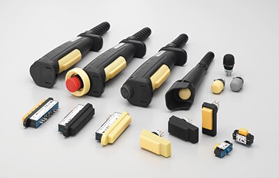
Enabling device
An additional manually operated device used in conjunction with a start control and which, when continuously actuated, allows a machine to function.
(The startup is performed with other devices.)
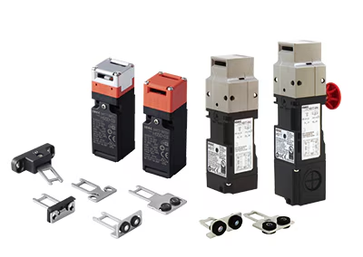
Interlocking device
A mechanical, electrical or other type of device, the purpose of which is to prevent the operation of hazardous machine functions under specified conditions.
Other requirements are provided in ISO 14119 (Safety of machinery - Interlocking devices associated with guards - Principles for design and selection). Please refer to the following link for further explanation of this standard.
Cableless control system (CCS)
This refers to control systems employing cableless (for example, radio, infra-red) techniques for transmitting control signals. Since there are no cables, it is necessary to clarify the target of control in order to avoid unintended dangerous situations where it is unknown which machine will start moving.
In addition, if the machine is allowed to be operated from multiple locations simultaneously, an intervention by another person may cause the machine to not operate as intended by the operator, putting the operator in a hazardous situation. Therefore, “single point control,” in which the machine is controlled from a single location, is required. Furthermore, no hazardous situation shall occur when the transmission of control commands or signals is interrupted or restored.
Control functions in the event of failure
Where failures or disturbances in the electrical equipment can cause a hazardous situation or damage to the machine or to the work in progress, the electrical equipment shall have appropriate functions to minimize the probability of the occurrence of such failures or disturbances.
Regarding the safety-related control functions, it is necessary to apply the requirements provided in ISO 13849-1 and IEC 62061.
Please refer to the following link for further explanation of ISO 13849-1 (Safety of machinery - Safety-related parts of control systems - Part 1: General principles for design).
8. Operator interface
Control devices for operator interface shall minimize the possibility of human errors (inadvertent operation) by, for example, positioning of devices, suitable design, and provision of additional protective measures. Therefore, ergonomic principles shall be taken into account.
Colors of actuators
The actuators, such as push-button switches, shall be color-coded according to the table below.
| Function | Color | Notes |
| Start/ON | Recommended: white, gray, black, or green Most preferred: white |
Shall NOT use: red |
| Emergency stop Emergency switching OFF |
Red actuator Yellow background |
|
| Stop/OFF | Recommended: black, gray, or white Most preferred: black |
Shall NOT use: green Recommended not to use red near emergency operation controls |
| Alternately switching between Start/ON and Stop/OFF | Recommended: white, gray, or black | Shall NOT use: red, yellow, or green |
| Hold-to-run | Recommended: white, gray, or black | Shall NOT use: red, yellow, or green |
| Reset | Required: blue, white, gray, or black | Shall NOT use: green |
| Reset and Stop/OFF | Recommended: white, gray, or black Most preferred: black |
Shall NOT use: green |
| Abnormal conditions/ Automatic cycle interruption |
Yellow |
Colors for indicator lights
Indicator lights should be color-coded with respect to the condition (status) of the machine in accordance with the table below.
| Color | Meaning | Explanation | Action by operator |
| Red | Emergency | Hazardous condition | Immediate action to deal with a hazardous condition (for example, switching off the machine supply, being alert to the hazardous condition and staying clear of the machine) |
| Yellow | Abnormal | Abnormal condition Impending critical condition |
Monitoring and/or intervention (for example, by re-establishing the intended function) |
| Blue | Mandatory | Condition that requires action by the operator |
Mandatory action |
| Green | Normal | Normal condition | Optional |
| White | Neutral | Other conditions When there are doubts about using red, yellow, green, or blue |
Monitoring |
Indicator light towers on machines should have the applicable colors in the following order from the top down: red, yellow, blue, green, and white.
9. Location, mounting, and enclosure of control devices
All controlgear shall be located and mounted so as to facilitate:
its accessibility and maintenance;
its protection against the external influences or conditions under which it is intended to operate;
operation and maintenance of the machine and its associated equipment.
To achieve the above, the requirements listed below shall apply.
Location and mounting of controlgear (11.2)
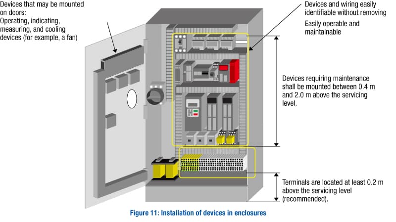
All items of controlgear shall be placed and oriented so that they can be identified without moving them or the wiring. For items that require checking for correct operation or that are liable to need replacement, those actions should be possible without dismantling other equipment or parts of the machine.
All controlgear shall be mounted so as to facilitate its operation and maintenance.
Where a special tool is necessary to adjust, maintain, or remove a device, such a tool shall be supplied.
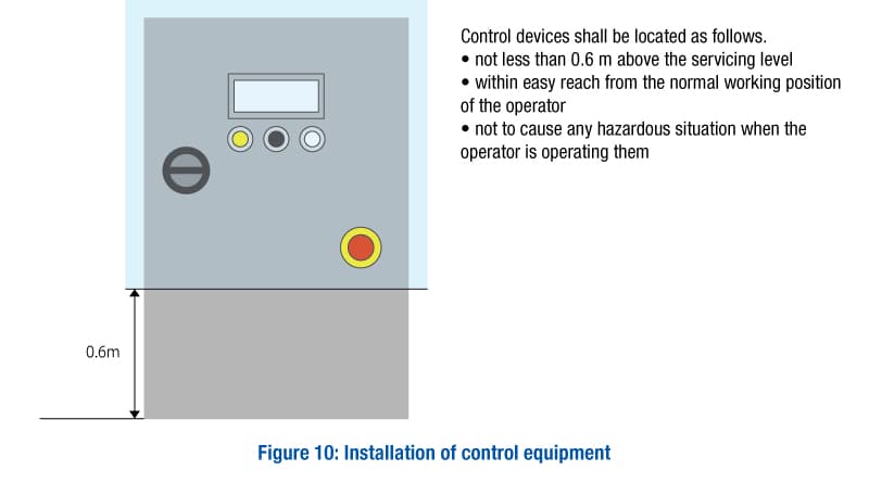
Where access is required for regular maintenance or adjustment, the relevant devices shall be located between 0.4 m and 2.0 m above the servicing level.
It is recommended that terminals be at least 0.2 m above the servicing level, and be placed such that conductors and cables can be easily connected to them.
No devices except devices for operating, indicating, measuring, and cooling shall be mounted on doors or on access covers of enclosures that are expected to be removed.
Plug-in devices that are handled during normal operation shall be provided with non-interchangeable features where an incorrect combination can result in malfunctioning.
Required specifications for enclosures (11.3, 11.4)
The protection of controlgear against ingress of solid foreign objects and of liquids shall be adequate, taking into account the external influences under which the machine is intended to operate (i.e. the location and the physical environmental conditions), and shall be sufficient against dust, coolants, lubricants and swarf.
Enclosures of controlgear shall provide a degree of protection of at least IP22 (for IP [ingress protection]). Please refer to the ‘Terms and definitions’ section of IEC 60204-1 for an explanation of IP.
Fasteners used to secure doors and covers should be of the captive type.
Windows of enclosures shall be of a material suitable to withstand expected mechanical stress and chemical attack.
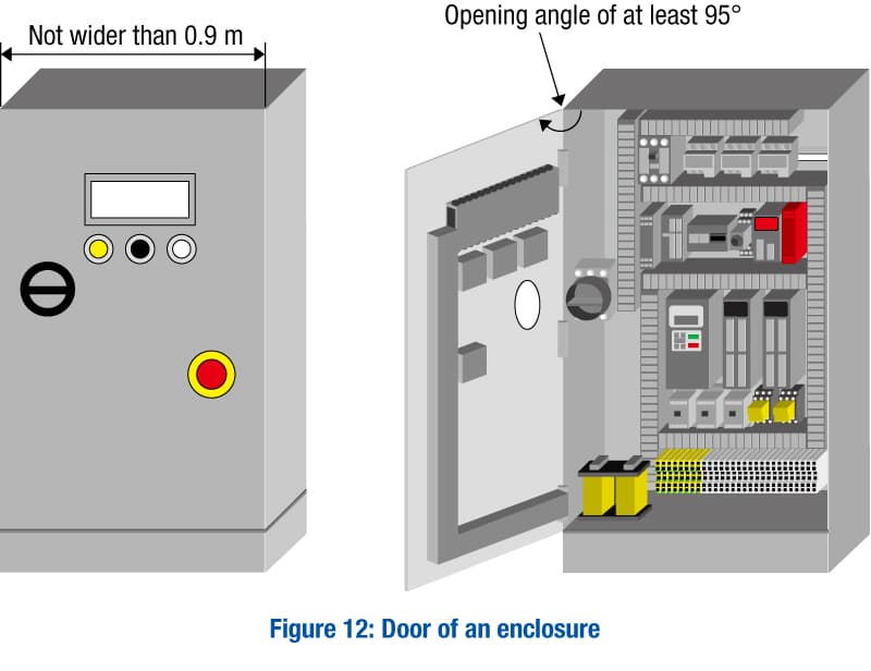
Doors of controlgear enclosures (recommended)
- installed with vertical hinges
- Width: 0.9 m or less
- Opening angle: 95° or more
Where openings in enclosures are provided (for example, for cable access), means shall be provided to ensure the degree of protection specified for the equipment.
Openings for cable lead-in shall be easily opened on site.
A suitable opening may be provided in the base of enclosures within the machine, so that moisture due to condensation can drain away.
10. Selection of cables
Conductors and cables shall be selected so as to be suitable for the operating conditions (for example, voltage, current, protection against electric shock, grouping of cables) and external influences (for example, ambient temperature, presence of water or corrosive substances, mechanical stresses, fire hazards) that can exist.
Conductors of cables
Conductors should be of copper.
To ensure adequate mechanical strength, the cross-sectional area of conductors should not be less than as shown in Table 5, in principle. (12.2).
| Location | Application | Type of conductor, cable (unit: mm2) | ||||
| Single core | Multicore | |||||
| Flexible (class 5 or 6) | Solid (class 1) or stranded (class 2) | Two cores, shielded |
Two cores, not shielded |
Three or more cores, shielded or not | ||
| Wiring outside (protecting) enclosures | Power circuit (fixed) | 1.0 | 1.5 | 0.75 | 0.75 | 0.75 |
| Power circuit (subjected to frequent movements) | 1.0 | ー | 0.75 | 0.75 | 0.75 | |
| Control circuits | 1.0 | 1.0 | 0.2 | 0.5 | 0.2 | |
| Data communication | ー | ー | ー | ー | 0.08 | |
| Wiring inside enclosures a) | Power circuit (fixed) | 0.75 | 0.75 | 0.75 | 0.75 | 0.75 |
| Control circuits | 0.2 | 0.2 | 0.2 | 0.2 | 0.2 | |
| Data communication | ー | ー | ー | ー | 0.08 | |
a) Excluding special requirements of individual product standards.
Insulation (coating) of cables
Insulation of cables and conductors shall withstand a test voltage (12.3):
- not less than 2,000 V AC for a duration of 5 min for operation at voltages higher than 50 V AC or 120 V DC; or
- not less than 500 V AC for a duration of 5 min for PELV circuitsThe mechanical strength and thickness of the insulation shall be such that the insulation cannot be damaged in operation or during laying. (12.3)
For the insulation of conductors and cables, it is necessary to consider hazards due to, for example, propagation of flames and emission of toxic and corrosive fumes (12.3).
Current-carrying capacity of cables
For the current-carrying capacity of conductors and wires, the main dependent factors, such as those listed below, shall be considered (12.4):
- the cross-sectional area of the conductor
- the insulation material (maximum allowable temperature and thermal conductivity of the insulation material)
- the ambient temperature (current-carrying capacity decreases with higher ambient temperature)
- the grouping of cables (current-carrying capacity decreases with denser arrangement, due to poor heat dissipation)
- the method of installation
Voltage drop
The voltage drop from the electrical supply point to the load shall not exceed 5% of the nominal voltage under normal operating conditions.
11. Wiring practices
It is necessary to consider the prevention of loosening and miswiring, as well as ease of maintenance.
Requirements for wiring
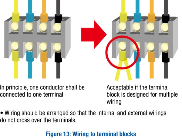
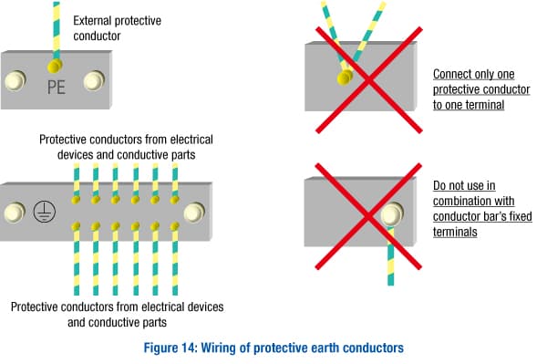
One conductor shall be connected to one terminal.
(Except for cases where the terminal is designed for connecting two or more conductors)
Only one protective conductor shall be connected to one terminal.
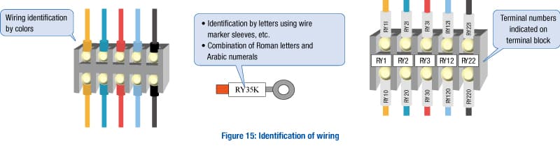
Terminals on terminal blocks shall be plainly marked or labelled to correspond with the identification used in the diagrams.
Numbers, alphanumeric characters, colors, or a combination of colors and numbers or alphanumeric characters may be used for identification. The numbers shall be Arabic; letters shall be Roman.
Where an incorrect electrical connection is identified as a source of risk, the conductors and/or terminations shall be identified.
The identification tags shall be legible, permanent, and appropriate for the physical environment.
Terminal blocks shall be mounted and wired so that the internal wiring and the external wiring do not cross over the terminals.
Conductors inside enclosures shall be supported where necessary.
Non-metallic ducts shall be made with a flame-retardant insulating material.
It is recommended that electrical equipment be mounted inside enclosures in such a way as to permit modification of the wiring from the front of the enclosure. If control devices are connected from the rear of the enclosure, a door or an outswing panel shall be provided.
Connections to devices mounted on doors or to other movable parts shall be made using flexible conductors.
Conductors and cables that do not run in ducts shall be adequately supported.
Terminal blocks or plug/socket combinations shall be used for control wiring that extends beyond the enclosure.
Wiring colors
The wiring shall be identifiable by marking or colors.
Colors that may be used: black, brown, red, orange, yellow, green, blue (including light blue), violet, gray, white, pink, turquoise (blue-green).
| For power supply | Wiring colors |
| AC power circuits | Black (light blue is recommended for neutral conductor) |
|
DC power circuits |
Black |
| Protective conductors | Bicolor combination of green and yellow |
| AC control circuits | Red |
| DC control circuits | Blue |
| Excepted circuits | Orange |
Protective conductors: the bicolor combination green and yellow (where one of the colors covers at least 30% and not more than 70% of the surface) is strictly reserved for protective conductors/protective bonding conductors.
12. Warning signs and markings
Warning signs, nameplates, markings, labels and identification plates shall be of sufficient durability to withstand the physical environment involved. (16.1)
| Enclosures that contain electrical equipment that can give rise to a risk of electric shock shall be marked with the graphical symbol shown to the right. |  |
| It is necessary to consider the possibility of hazardous surface temperatures of the electrical equipment, due to the heat-generating components of electrical equipment. The temperature of parts that may be touched by persons shall not exceed the limit values specified in ISO 13732-1. Parts where the limit values may be exceeded shall be provided with protective measures to prevent unintended contact or marked with the graphical symbol shown to the right. |
 |
13. Technical documentation
The following information shall be legibly and durably marked in a way that is plainly visible after the equipment is installed on enclosures that receive incoming power supplies:
name or trade mark of supplier
certification mark or other marking that can be required by local or regional legislation, when required
type designation or model, where applicable
serial number, where applicable
main document number (refer to IEC 62023), where applicable
rated voltage, number of phases and frequency (if AC), and full-load current for each incoming supply
The following technical documentation shall be supplied:
a) where more than one document is provided, a main document for the electrical equipment as a whole, listing the complementary documents associated with the electrical equipment;
b) identification of electrical equipment (see 16.4)
c) information on installation and mounting including:
a description of the electrical equipment’s installation and mounting, and its connection to the electrical supplies (and, where relevant, other supplies);
short-circuit current rating of the electrical equipment for each incoming power supply;
rated voltage, number of phases and frequency (if AC), type of distribution system (TT, TN, IT) and full-load current for each incoming supply;
any additional electrical supply(ies) requirements (for example, maximum supply source impedance, leakage current) for each incoming supply;
space required for the removal or servicing of the electrical equipment;
installation requirements, where needed, to ensure that the arrangements for cooling are not impaired;
environmental limitations (for example, lighting, vibration, EMC environment, atmospheric contaminants) where appropriate;
functional limitations (for example, peak starting currents and permitted voltage drop(s)) as applicable;
precautions to be taken for the installation of the electrical equipment relevant to the electromagnetic compatibility;
d) an instruction for the connection of simultaneously accessible extraneous-conductive parts in the vicinity of the machine (for example, within 2.5 m) such as the following to the protective bonding circuit:
metallic pipes;
fences;
ladders;
handrails.
e) information on the functioning and operation, including as applicable:
an overview of the structure of the electrical equipment (for example, by structure diagram or overview diagram);
procedures for programming or configuring, as necessary for the intended use;
procedures for restarting after an unexpected stop;
a sequence of operation;
f) information on maintenance of the electrical equipment, as appropriate, including:
frequency and method of functional testing;
instructions on the procedures for safe maintenance and where it is necessary to suspend a safety function and/or protective measure (see 9.3.6);
guidance on the adjustment, repair, and frequency and method of preventive maintenance;
details of the interconnections of the electrical components subject to replacement (for example, by circuit diagrams and/or connection tables);
information on required special devices or tools;
information on spare parts;
information on possible residual risks, indication of whether any particular training is required, and specification of any necessary personal protective equipment;
where applicable, instructions to restrict availability of key(s) or tool(s) to skilled or instructed persons only;
settings (DIP-switches, programmable parameter values, etc).
We provide a wide range of help and resources:
If you have questions or suggestions, we're here to listen.
Our sales and support teams are on hand to help.
All the technical documentation you need.