
The A-Z of e-stops: important, unique, safe and convenient features of emergency stop switches (part 1)
Date: 10/02/2026 | By: IDEC HQ
Whatever your industrial safety system looks like, wherever you decide to install an emergency stop switch (e-stop) it’s always going to stand out.
In fact, it has to. E-stops must be highly recognizable, and quickly and easily identifiable in dangerous situations.
In this 2-part series, we’ll run through an A-Z of features that set emergency stop switches apart and make them essential safety devices for industrial applications. This article covers the first half of the alphabet, from A to M – check back for the remaining letters (N to Z) in the next article.
Contents (part 1):
A is for: accident prevention
B is for: B10d
C is for: compatibility (with systems, devices, and your application)
D is for: direct opening action
E is for: EMO
F is for: foreseeable failures
G is for: guards and enclosures
H is for: human intervention
I is for: international safety standards
J is for: just in case
K is for: “kill switch”
L is for: latching
M is for: manual reset
N is for: normally closed (NC) contacts
O is for: operator
P is for: Performance Level
Q is for: qualified personnel
R is for: reset methods
S is for: Safe Break Action
T is for: technological advancements
U is for: “unintended actuation”
V is for: visibility
W is for: waterproofing
X is for: XA/XW series e-stops
Y is for: yellow
Z is for: zoning
A is for: accident prevention
Several types of industrial safety devices are designed to directly prevent accidents and injury. The main advantage of an emergency stop switch is that it cuts power to the connected machine or equipment immediately when needed.
B is for: B10d
‘B10d’ is shorthand for the number of operation cycles before dangerous failure (before 10% of the device’s components fail).
The value of B10d depends on factors including the type of device, the current, and how often the device is used. A typical B10d value for an emergency stop switch is 100,000 cycles – that’s assuming the switch has direct opening action, which is explained below.
Learn more about assessments and Performance Level calculations for the safety-related parts of control systems (SRP/CS) on our page about the SISTEMA library.
C is for: compatibility (with systems, devices, and your application)
For an e-stop to work effectively, it must be compatible with the rest of your safety system (including controls), the use environment, and the power supply (including any backup systems). Luckily, that isn’t difficult – emergency stop switches are mandatory in many setups, so they’re designed for simple integration.
Many emergency stops have a standardized appearance, as well as straightforward wiring, so the main points to confirm are:
Current and voltage
Mounting hole size
Depth (in relation to control panel thickness)
Wiring terminal type
IP ratings for water/dust resistance
The catalog and/or datasheet for the e-stop you’re considering will have all the technical information you need to make the best choice.
D is for: direct opening action
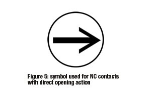
This mechanism works to ensure that the ‘normally closed’ (NC) contacts open when the switch is pressed. It uses the direct force of the press action – with no reliance on springs or other flexible/elastic parts, which are more resilient and might fail to activate.
You can identify emergency stop switches with the direct opening action mechanism by looking for the registered symbol.
E is for: EMO
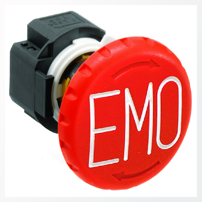
‘Emergency (switching) off’ (often shortened to EMO) and ‘emergency stop’ are slightly different functions.
Emergency off: cuts the power to the machine in case of danger (electrical hazards)
Emergency stop: stops all machine motion that poses a risk of danger (physical hazards)
‘Emergency off’ shuts down the power supply to the whole system, but may not immediately stop the machine (some parts may keep moving due to inertia).
‘Emergency stop’ prevents dangerous motions that could harm operators, but is designed to only cut power to specific circuits (power supply may remain active).
F is for: foreseeable failures
The 2 main types of ‘foreseeable failure’ are:
Failure during installation: the e-stop is installed incorrectly (contact block/wiring issues), or in a place that’s difficult and inconvenient to access.
Failure during operation: the e-stop is pressed or hit with too much force, causing an impact (shock) that damages the switch.
Another predictable risk in large-scale operations is failure caused by pressing the wrong switch. On production lines, around large machinery, and when partial equipment stops are needed, multiple emergency stop switches are common. Which one stops which part of the machine?
The best locations for your e-stops should be decided after a full risk assessment.
G is for: guards and enclosures
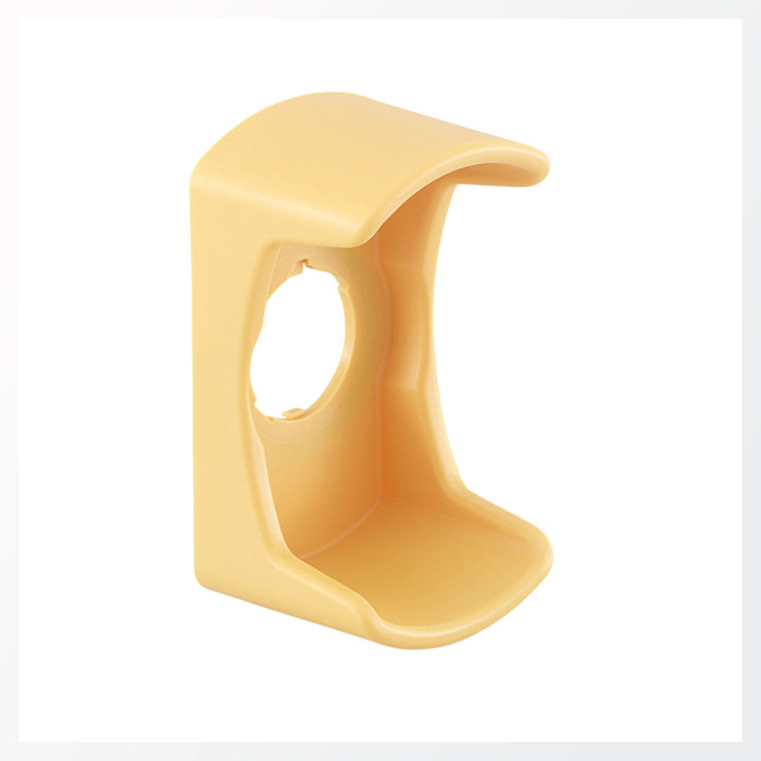
A switch guard – also known as a protective shroud – can be used to prevent ‘unintended actuation’ of an emergency stop device (explained further down).
Protective shrouds are typically shaped to make the switch harder to press by accident, and to prevent it from being hit by moving/falling items. However:
the e-stop function must not be impeded or otherwise affected,
the e-stop’s visibility and accessibility must be maintained, and
the e-stop and guard must be installed correctly.
There are some standardized requirements for the color and diameter of the guard, and how far the e-stop switch should be recessed into it.
H is for: human intervention
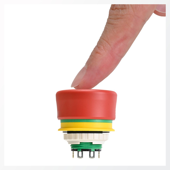
No matter when or why the e-stop needs to be pressed, it must be an intentional human action.
This “single human action” makes the emergency stop function as simple – and as intended – as possible. It’s easy to see and activate in an emergency, and it’s used with purpose by operators who recognize danger and understand the need to take urgent action.
I is for: international safety standards
The safety requirements for e-stops are covered by various standards:
ISO 12100 (Safety of machinery – General principles for design – Risk assessment and risk reduction),
ISO 13849-1 (Safety of machinery – Safety-related parts of control systems, Part 1: General principles for design),
ISO 13850 (Safety of machinery – Emergency stop function – Principles for design),
IEC 60947-5-1 (Low-voltage switchgear and controlgear – Part 5-1: Control circuit devices and switching elements – Electromechanical control circuit devices), and
IEC 60947-5-5 (Low-voltage switchgear and controlgear – Part 5-5: Control circuit devices and switching elements – Electrical emergency stop device with mechanical latching function).
Requirements for many of the points above (e.g. guards, EMO markings, direct opening action) and below are mentioned in at least 1 of these standards.
J is for: just in case
E-stops are intended as the last line of defense – a secondary safety measure, only used if other safety devices fail. E-stops are essential for worker safety and peace of mind, but should always be the final possible measure to avoid an accident.
In an ideal world, you’d never press one.
K is for: “kill switch”
The informal name for an emergency stop switch, an EMO switch, or an ‘emergency power off’ (EPO) switch. Pressing it interrupts the power supply to the connected equipment – instantly ‘killing’ the power.
Non-safety shutdown switches and other processes take more time, cutting off power to machines and systems in a way that won’t damage them. In situations where an e-stop makes the difference, the highest priority is keeping workers safe from injury – even if the power interruption causes issues with the machinery.
L is for: latching
Once an emergency stop switch has been pressed, it stays latched (locked) in that position. Latching is a key function for e-stops, as it holds the machine in a stopped state. Standard stop switches may not have a latch mechanism.
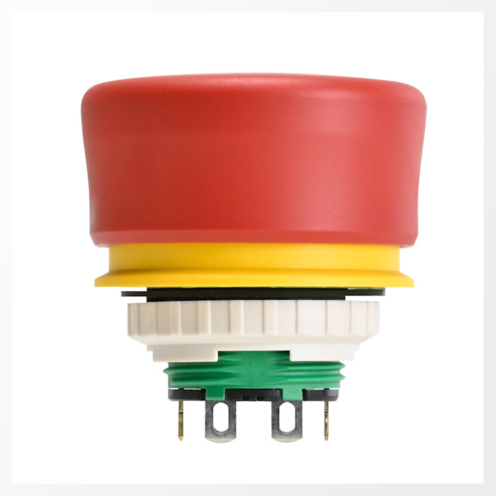
M is for: manual reset
“The emergency stop function shall be reset by intentional human action.” – from ISO 13850, which also specifies the “single human action” for activation.
In the same way that an emergency stop must be intentionally pressed, the reset (unlatching) must also be deliberate.
ISO 13850 also states a requirement to confirm safety before resetting an emergency stop switch, and that the need to inspect the machine should be included in the instructions for use.
A break in the safety action: make sure to read part 2
We’ve got half of the contents list left to cover – don’t miss part 2 of this article series. You can also start exploring IDEC’s emergency stop switches and EMO switches online, or get in touch with your regional sales team.
We provide a wide range of help and resources:
If you have questions or suggestions, we're here to listen.
Our sales and support teams are on hand to help.
All the technical documentation you need.