ISO13850 | EMEA
ISO 13850, “Safety of machinery — Emergency stop function — Principles for design”, is a standard (type-B) that describes the safety requirements for designing emergency stop devices of machinery. Based on the risk assessment, perform risk reduction measures as necessary. The emergency stops function falls under the complementary protective measures among the protective measures.
For an explanation of the risk assessment and protective measures, check the following link.
The emergency stop function is designed to avert actual or impending emergency situations arising from the behavior of persons, or from an unexpected hazardous event, by intended human operation of the emergency stop switch. Therefore, it is necessary to prioritize the emergency stop function over all other functions and operations in all operation modes of the machine without impairing other protective functions (for example, functions to release a person trapped by the machine or extinguish fire).
In addition, it is also necessary that the machine is maintained in the stop position until the emergency stop switch is reset (described as “unlatched” in the standard) by an intended action of operators.
For this reason, it is necessary that the emergency stop function complies with the following safety requirements.
1 Intended actuation
1.1 Recommended actuators and nameplates
Since it is necessary that the emergency stop switch is operated by an intended action as fast as possible in an impending emergency situation, its operability/visibility should be optimized, and it should be actuated without hesitation.
For this reason, the following safety requirements are included.
ISO13850:2015 (JIS B9703:2019)
4.1.1.2 The emergency stop function shall be available and operational at all times.
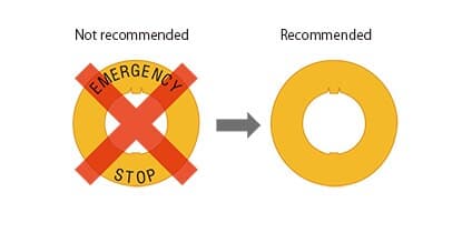
4.3.6 The actuator of the emergency stop device shall be coloured RED. As far as a background exists behind the actuator and as far as it is practicable, the background shall be coloured YELLOW.
4.3.7 Neither the actuator nor the background should be labelled with text or symbols.
When it is necessary to identify the direction of unlatching of the actuator (button) then this identification shall have the same or nearly the same colour as the actuator.
Accordingly, it is recommended not to display text or symbols such as EMERGENCY STOP on the actuator or nameplate of an emergency stop device. In order to accommodate the diversity of languages used by machine operators, this recommendation is based on an intention to enable workers to have the following common recognition without the need to recognize texts or symbols:

A combination of a red actuator and yellow background = Emergency stop device (even if there are no texts/symbols)
For example, when a person intends to actuate an emergency stop switch, the operator may momentarily hesitate in the actuation if the switch displays texts/symbols that the person cannot read/understand, delaying the actuation of the emergency stop device. Even if the displayed texts can be read/understood, it is also expected that actuation following the recognition of only the color combination of red and yellow is faster than actuation following the recognition of texts/symbols.
For this reason, use one of the blank nameplates shown below when using a nameplate for an emergency stop switch.
| Hole Size | Description | Legend | Part No. | Material | Plate Color |
| Ø16 | For Ø30 Operator | (blank) | HAAV-0 | Polyamide | Yellow |
| For Ø40 Operator | HAAV4-0 | ||||
| Ø22 | For Ø40 Operator | HWAV-0-Y | Polyamide | ||
| For Ø60 Operator | HWAV5-0 | PBT | |||
| Ø30 | - | HNAV-0 | Polyamide |
Furthermore, in order to prevent operators from hesitating in the actuation of an emergency stop switch, it is required that arrows showing the direction of unlatching the emergency stop switch should not be too conspicuous. The reason is that some workers may mistakenly think that such arrows indicate the direction of actuating the emergency stop switch.
1.2 Location of emergency stop devices
Since emergency stop switches are mainly used in an emergency situation, there are safety requirements concerning their locations to ensure that they can be actuated as fast as possible.
ISO13850:2015(JIS B9703:2019) |
For new and/or existing machines, confirm that emergency stop switches are located at locations which satisfy the above safety requirements. Confirm that emergency stop switches are located near the work locations and can be actuated not only during stationary time, such as automatic operations, but also during non-stationary work, such as machine setup and maintenance.
2 Prevention of unintended actuation
Until the revisions of the ISO standards in 2015 and the JIS standards in 2019, the use of a switch guard (used synonymously with protective shroud) with an emergency stop switch has not been permitted for machinery subject to the standards such as machine tools and food machinery.
However, these revisions have allowed the use of a switch guard (protective shroud) under certain conditions, because the “Prevention of unintended actuation of emergency stop devices” is added as a safety requirement.

ISO13850:2015(JIS B9703:2019 |
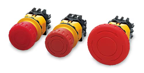
If it is determined that a switch guard (protective shroud) is necessary after considering the location of the emergency stop switches in Section 4.3.2 and the prevention measures against unintended actuation in Section 4.5, use one from the following combinations of the switch guards and the emergency stop switches.
The following combinations have been confirmed by TÜV Rhein land for complying with the requirements of emergency stop switches with a protective shroud, specified by ISO 13850:2015.

3 Intended resetting
3.1 Importance of human intention in resetting
Since an emergency stop switch is primarily used by an intended action during an emergency situation, the importance of an intended action in its resetting the emergency stop switch is also described in the safety requirements.
ISO13850:2015(JIS B9703:2019) 4.1.1.2 |
3.2 Description concerning reset in the instruction manual
Since an emergency stop switch is primarily used in an emergency situation, information concerning machine reset is described in the safety requirements.
ISO13850:2015(JIS B9703:2019) 4.1.4 Disengagement (e.g. unlatching) of the emergency stop device |
The actuation of an emergency stop switch means that there is a possibility that an emergency situation has occurred. Therefore, before resetting the emergency stop switch, it is necessary to check the cause of the actuation and confirm that safety is ensured. Since it is necessary to disseminate this information to users, the instruction manual must describe the inspections required after actuating and before resetting emergency stop switches.
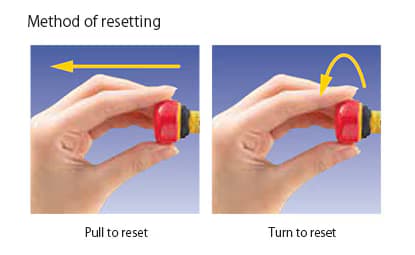
3.3 Unrecommended reset type
The use of some emergency stop devices is no longer recommended after the revision. Although their use is not prohibited, the following conditions must be satisfied to use those devices.
ISO13850:2015(JIS B9703:2019) 4.3.6 |
These safety requirements were added because of the following. A key to reset the emergency stop switch may be left inserted into an actuator. If a person unaware of the situation operates the emergency stop switch without thinking carefully in an emergency, the person can injure his/her hand with the key inserted into the actuator. Therefore, the use of the key reset type emergency stop switch is no longer recommended.
In addition, when using a key reset type emergency stop switch after performing the risk assessment, implement measures based on the above safety requirements.
4 Prevention of unintended reset
As described above, human intention plays an important role in the emergency stop function. Intended actuations, prevention of unintended actuations, and intended reset operations are specified in the standards. Note that prevention of unintended reset operations is not specified as a safety requirement.
However, “Prevention of unintended reset operation” and the “Intended reset operation” are both important as a practical matter. The prevention of an unintended reset operation requires special attention if multiple persons enter a danger zone, for example, during machine setup or maintenance. In order to prevent an unintended reset, the key reset type emergency stop switches, shown in Section 3.3, have conventionally been used. As mentioned above, this is no longer recommended. Therefore, another measure to prevent an unintended reset is necessary.
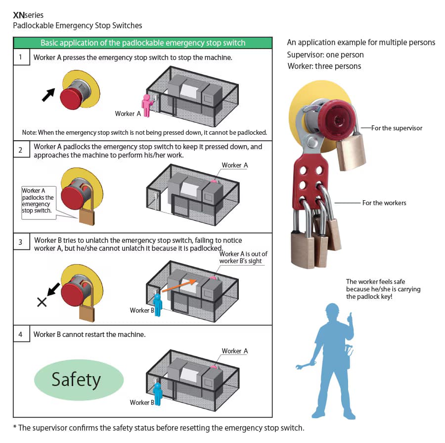
The use of a padlock to protect the emergency stop switch is one such alternative measure. As shown in the figure below, only after actuating the emergency stop switch, each worker can padlock the switch with his/her own padlock. By keeping the key to himself/herself, an unauthorized reset by other workers can be prevented. Since the machine will not be restarted, each worker can ensure his/her own safety.
5 Span of control of emergency stop device(s)
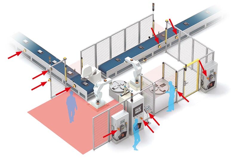
In principle, when actuating an emergency stop device, the entire machine system should be stopped. However, stopping a complicated machine or machine system entirely could create additional hazards or unnecessarily affect production. In such a case, it is possible as an exception to set the “Span of control” to partially stop the machine or machine system as shown below.
ISO13850:2015(JIS B9703:2019) 4.1.2 |
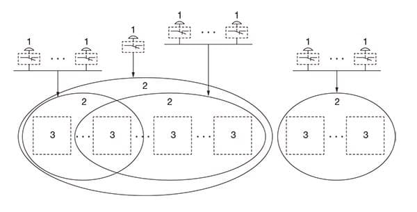
Examples demonstrating the concept of span of control Key:
1: emergency stop device
2: span of control
3: section of machine or machine
This safety requirement allows precise setting of the span of the machine that is stopped by an emergency stop device according to the actual situation.
Implement measures based on the above safety requirement before setting the span of control.
6 Required performance level (PLr), safety integrity level (SIL)
The minimum required performance level (PLr) and safety integrity level (SIL) required for the emergency stop function are specified as follows.
ISO13850:2015(JIS B9703:2019)
4.1.5 Emergency stop equipment
4.1.5.1 The safety related parts of the control system or subsystems which perform the emergency stop function shall comply with the relevant
requirements of ISO 13849-1 and/or IEC 62061.
Determination of the Performance Level (PL) or SIL required should take into account the purpose of the emergency stop function, but the minimum required is PLr c or SIL 1.
Depending on the result of the risk assessment and the safety requirements of the type-C standards for the subject machinery, a minimum of PLr = c or SIL 1 is required for the emergency stop function.
For an explanation of PLr and SIL, check the following link.
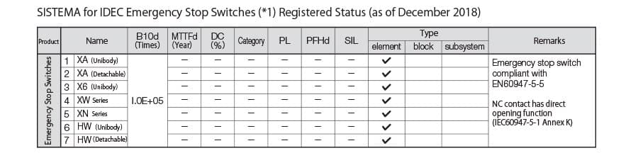
Also, in the support software SISTEMA for the safety evaluation according to ISO 13849-1 and/or IEC 62061, the following emergency stop switches are registered.
7 Emergency stop function on portable operator control stations
Following advancements in technology, user demand has risen, such as the use of the cable detachable type so that one teaching pendant can be used with multiple robots or improvement in convenience by eliminating the wiring.
However, since safety aspects must be considered carefully, the contents for detachable and wireless operator control stations have been updated in this revision as follows.
ISO13850:2015(JIS B9703:2019) |
The above safety requirement aims to prevent accidents when mistakenly operating the inactive emergency stop devices on the detachable teaching pendants or cableless operator control stations. Implement measures based on the above safety requirement when choosing a detachable teaching pendant or cableless operator control station.
We provide a wide range of help and resources:
If you have questions or suggestions, we're here to listen.
Our sales and support teams are on hand to help.
All the technical documentation you need.