What is a force-guided relay? | EMEA
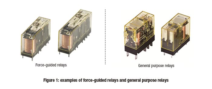
Figure 1 shows examples of force-guided relays and general purpose relays.
There are various types of relays, but the safety-related part of a control system (SRP/CS) for machines uses force-guided relays.
A force-guided relay’s main purpose is for switching contacts. If a welding fault occurs in the NO contact causing an ON state, a force-guided relay also maintains the OFF state of the NC contact through a guiding mechanism.
Design and operation of force-guided relays
Table 1 shows the design and operation of force-guided relays.
In a force-guided relay, the normally open (NO) and normally closed (NC) contacts are separated by a barrier and insulated from each other. The NO and NC contacts are connected mechanically, linked by a crossbar or other guiding mechanism. They operate in tandem, based on whether voltage is being supplied to the coil or not.
The key feature of force-guided relays is that, if the NO contact is welded shut, this guiding mechanism keeps the NC contact open (state 3, as shown in table 1 below).
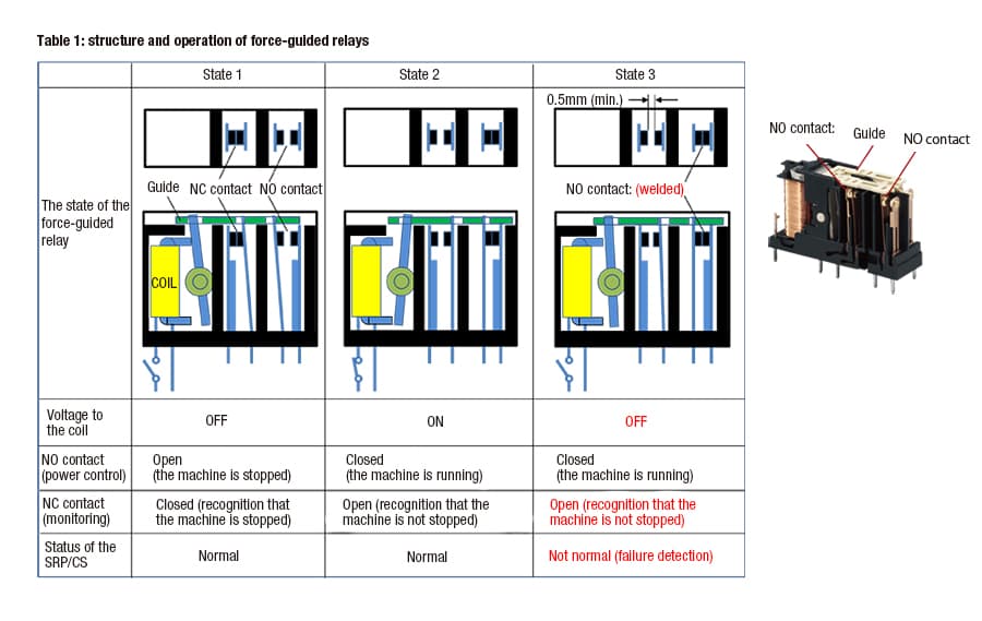
In table 1, the principles of how a force-guided relay works are illustrated with 1 NO contact and 1 NC contact. However, actual products typically use a set of 3 NO contacts with 1 NC contact.
As shown in figure 2, K1 and K2 are examples of force-guided relays used in real-world situations. Each relay has 3 NO contacts connected to a 3-phase AC power control circuit (e.g., a motor) and 1 NC contact connected to the monitoring circuit (between S33 and S34, also as shown in figure 2).
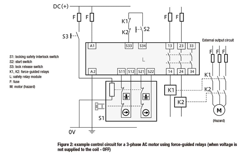
By setting up the connections in this way, the machine is stopped when voltage is not supplied to the coil (OFF, state 1 as shown in table 1). The machine can be operated only when voltage is supplied to the coil (ON), as this enables the NO contacts to close (state 2 as shown in table 1).
Using NO contacts in the power circuit makes it easier to ensure safety. This is because the NO contacts open when voltage is not supplied to the coil (OFF) due to disconnected wires or other causes. When the NO contacts open, the machine is stopped.
When this happens, the NC contact is closed when voltage is not supplied to the coil (OFF, when the machine is stopped, state 1 as shown in table 1). The NC contact is open when voltage is supplied to the coil (ON, state 2 as shown in table 1).
If an NO contact in K1 is welded shut (state 3 as shown in table 1), the NC contact for K1 in the monitoring circuit remains open even if voltage is not supplied to the coil. This is because the NC contact operates in tandem with the guiding mechanism.
When this happens, K2 is still operating normally. This means that the machine can be stopped by opening K2’s 3 NO contacts.
Connecting K1 and K2’s NC contacts to the monitoring circuit in series means that the machine cannot run even if the S2 start switch is pressed. As the K1’s NO contact is welded shut, the NC contacts remain open. As a result, the K1 force-guided relay must be replaced with a new one before the machine can be restarted.
All of this means that, by using two force-guided relays, the machine can be stopped even if an NO contact is welded shut. Restart can also be prevented, helping to maintain machine safety.
Other types of failure: broken leaf springs
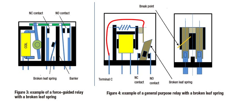
From a safety perspective, leaf spring breakages are one of the most important types of system failure to consider. Figures 3 and 4 show a force-guided relay and a general purpose relay respectively, each with a broken leaf spring.
As the NO and NC contacts in a force-guided relay are separated by a barrier, if the leaf spring for one of the contacts breaks the other contact is not affected. This minimizes the impact of a breakage.
In a general purpose relay, the NO and NC contacts are part of the same unit and connected to a C contact. This means that a broken spring can cause both contacts to become conductive. This may affect adjacent systems – for example, causing a machine to move in an unexpected and unintended way, or making a machine impossible to stop.
For this reason, general purpose relays cannot be used in the safety-related part of a control system.
IDEC force-guided relays
We provide a wide range of help and resources:
If you have questions or suggestions, we're here to listen.
Our sales and support teams are on hand to help.
All the technical documentation you need.