
What is a non-contact safety interlock switch? | USA
A non-contact safety interlock switch detects the distance between a door-mounted actuator and a sensor head mounted to the machine/equipment. The sensor head is used to detect information from the actuator without direct contact, and this signal is transmitted as data (the door’s ‘open’ or ‘closed’ status).
One feature of this type of interlock switch is that the actuator and sensor head never touch, so there is no debris created through surface wear and tear. In addition, the switch has no openings and minimal uneven surfaces, granting it higher resistance to water and dust.
Non-contact safety interlock switch types
As shown in the table below, safety interlock devices that detect door opening and closing without physical contact are classified as type 3 and type 4 interlock devices under ISO 14119 (Safety of machinery – Interlocking devices associated with guards – Principles for design and selection).
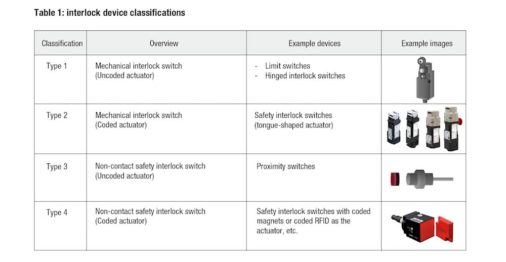
Note: coded actuators are specifically designed to activate certain interlock devices.
As the interlock device can only be activated with a specific combination, it is effective for preventing overrides with keys, coins, tools, and other objects. (Under ISO 14119, this is referred to as “defeat”.)
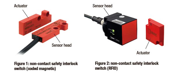
IDEC offers two types of non-contact safety interlock switches, both classified as type 4 interlock devices. One is a coded magnetic non-contact safety interlock switch, and the other is an RFID non-contact safety interlock switch (see figures 1 and 2 below).
Reliability is essential for all non-contact safety interlock switches, and they must also have the following features:
Defeat protection
Fault detection (stops the machine when a fault is detected, and maintains the stopped state until the fault is resolved)
Non-contact safety interlock switch (coded magnetic)
Design features and operation
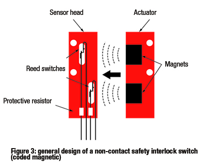
Figure 3 shows the general design of a coded magnetic non-contact safety interlock switch. It has a sensor head with multiple reed switches, and a paired actuator with multiple magnets that correspond to the switches.
The sensor head is mounted on the machine/equipment, and the paired actuator is mounted on the door. When the door is closed, the magnetic field around the sensor head becomes stronger, activating the reed switch contacts. When the door is opened, the magnetic field weakens, and the contacts return to their original state.
Defeat prevention
If there is only one magnet and reed switch pair, the switch contact can easily be activated without the actuator by bringing any commercially available magnet close to it. For this reason, magnetic non-contact safety interlock switches use at least two pairs of magnets and reed switches.
The switch is considered to be in a ‘normal’ state only when all pairs are activated. This is a measure to prevent defeat using commercially available magnets or other objects.
The reed switch has a ‘normally open’ (NO) contact (open when the door is open) and a ‘normally closed’ (NC) contact (closed when the door is open). Using both NO and NC contacts prevents the switch from being defeated due to short-circuiting the wiring.
However, even if all of the above defeat prevention measures are taken, the possibility of defeat (e.g. with a replacement actuator, or by removing the actuator from the door) remains. Therefore, it is essential to have a safety management system in place that includes measures preventing the actuator from being removed from the door and the management of replacement actuators.
Read our explanation of ISO 14119 for more information:
Fault detection
Coded magnetic non-contact safety interlock switches are typically used in combination with a controller (a safety relay module). The main reason for this is that the reed switch contacts do not have direct opening action. In this case, if a contact is welded shut, it may not be possible to stop the machine.
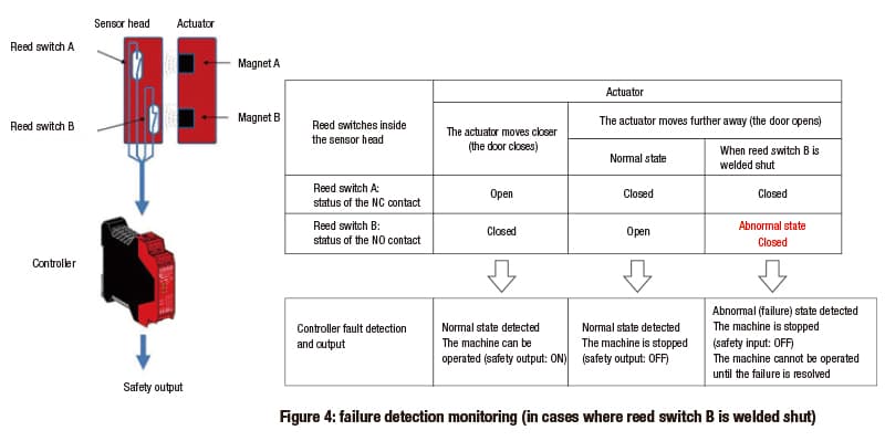
In order to detect this type of failure (welded contact*), the signal combination from the two reed switch circuits in the safety interlock switch must be monitored by the controller. If the controller detects an abnormal signal combination, it determines that a failure (welded contact) has occurred and stops the safety output. This stops the machine.
* a state where the surface of the contact melts, cools and then sticks together, e.g. due to an inrush current exceeding capacity during contact opening/closing.
Figure 4 provides an outline of this concept. In figure 4, it is assumed that one of the two circuits (reed switch B) has a welded contact.
Note that, even if the signals for two circuits are being monitored, if both circuits fail at the same time this simultaneous failure cannot be detected. As a result, the reed switch has a ‘normally open’ (NO) contact (open when the door is open) and a ‘normally closed’ (NC) contact (closed when the door is open). Both NO and NC contacts are used to prevent a situation/state where the switches fail at the same time.
Features and applications
As mentioned above, non-contact safety interlock switches do not create debris because there is no physical contact and wear. This makes these switches suitable for use in safety applications such as cleanrooms for semiconductor manufacturing, which require a clean production environment.
In addition, non-contact safety interlock switches have a relatively smooth surface. This makes it more difficult for particles and other foreign matter to accumulate and adhere to the sensor head or actuator. These switches are suitable for use in safety applications such as food production, where it is essential that equipment can be thoroughly washed.
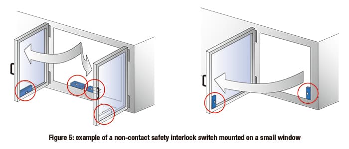
Generally, non-contact safety interlock switches can be much smaller than mechanical safety interlock switches. This means they can be installed on windows with a small opening radius, as shown in figure 5. In addition, there is more room to achieve mounting position accuracy compared to using mechanical interlock switches.
Usage notes
As the actuator contains magnets, if there are other magnets or ferromagnetic materials (such as steel plates) nearby, the non-contact safety interlock switch must be placed at a distance where it will be unaffected. It is also important to avoid using ferromagnetic materials for the screws used to mount the sensor heads and actuators to machinery and equipment.
Coded magnetic non-contact safety interlock switches cannot be used in environments where ferromagnetic, metal-based powders (such as iron powder) are present in the surrounding environment. In addition, as non-contact safety interlock switches are characterized by their lack of physical contact, they do not have a physical locking mechanism. This means that, if a door needs to be physically locked, a separate locking device (e.g. a cylindrical lock) is required.
Non-contact safety interlock switch (RFID)
Design features and operation
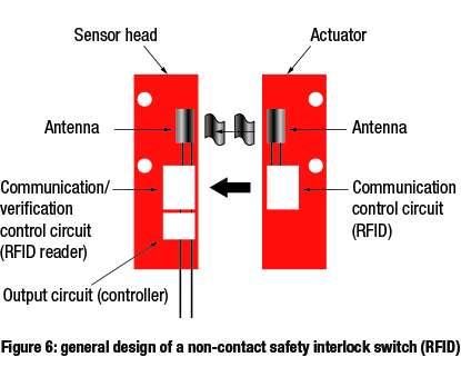
Figure 6 shows the general design of an RFID non-contact safety interlock switch.
When the door-mounted actuator gets close enough to the sensor head mounted on the machine, the RFID reader inside the sensor head reads the identifying data from the RFID tag inside the actuator.
This is checked against the identifying data stored in the sensor head. If it matches, this information is transmitted as data (the door’s ‘closed’ status).
Defeat prevention
RFID non-contact safety interlock switches have two types of defeat functions: unicode and multicode.
Unicode
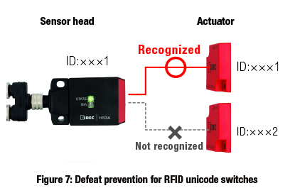
This function transmits data (that the door is closed) only when the RFID reader has read the specific RFID code for the actuator it was paired with at the outset (as shown in figure 7). If an actuator that has not been paired with the switch is close to the sensor head, the door will not be recognized as closed.
This method allows defeat prevention measures to be implemented at an extremely high level. It makes the most effective use of the RFID switch type’s features. However, users must take measures to prevent the actuator from being removed from the door.
Multicode
This function transmits data (that the door is closed) even if different actuators with the same RFID code are used.
This method also enables a higher level of defeat prevention (higher level of coding) than magnetic switches.
However, as with magnetic switches, a safety management system is essential. This system must include measures to prevent the actuator from being removed from the door, and management of replacement actuators.
Fault detection
Both the unicode and multicode types can detect faults independently, using the sensor head’s embedded control function (built-in IC and software). As a result, there is no need to use an external controller for fault diagnosis.
Summary
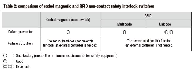
The table below contains a comparison of defeat prevention and fault detection for non-contact safety interlock switches (magnetic and RFID).
IDEC non-contact safety interlock switches
We provide a wide range of help and resources:
If you have questions or suggestions, we're here to listen.
Our sales and support teams are on hand to help.
All the technical documentation you need.