What is a safety interlock switch? | APAC
Contents
Safety interlock switches (door interlock devices)
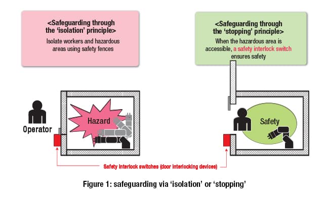
In many cases, when a human approaches machinery or equipment that is running, there is the possibility of a serious accident occurring. To prevent this, safety must be ensured through isolation – putting distance between people and running machinery/equipment.
However, there are times when work must be done inside this machinery (e.g. maintenance, parts replacement and/or adjustments, cleaning, etc.). In these cases, safety must be ensured by bringing the machine to a complete stop before a human enters it (see figure 1).
This is known as safeguarding using the principles of “isolation” and “stopping”, and forms the basic concept for ensuring machinery safety.
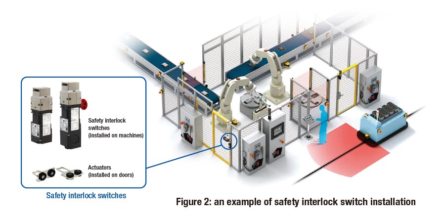
Safety interlock switches (also known as door interlock or guard interlock devices/systems) are installed on the front-facing door of machine tools or the door area of safety enclosures around industrial robots. They are used to detect whether the door is open or closed (see figure 2).
In other words, the safety interlock switch is a safety-related part of a control system. It only allows the machinery to run when the door is closed, and maintains a stopped state when the door is open.
Control using safety interlock switches
There are two main types of safety interlock switch: with and without locking functions.
The type without a lock allows the door to be opened at any time regardless of the machine’s operational status. The type with a lock only allows the door to be opened under certain conditions.
Below is a diagram and explanation of the basic non-locking switch.
The safety interlock switch is designed so that the switch body and dedicated actuator are separate, as shown in figure 2. The switch body is mounted to the machine, and the actuator is mounted to the door.
The switch body’s internal contact turns on and off based on whether the door is open or closed (whether the actuator is inserted into the switch body or not). The contact signal is transmitted as an indication of the door’s ‘open’ or ‘closed’ status.
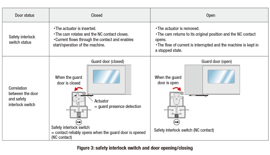
The diagram on the left-hand side of figure 3 shows the status of the safety interlock switch when the door is closed. The diagram on the right-hand side shows the status of the switch when the door is open.
When the door is closed (as shown on the left), the actuator mounted to the door rotates the internal cam. The ‘normally closed’ (NC) contact is switched on by the force of the spring, causing current to flow through the circuit. In this state, the control system determines that the door is closed and that the machine can be operated.
On the other hand, when the door is open (as shown on the right), the actuator rotates the internal cam in a way that pushes down the NC contact. The NC contact is pushed into the OFF position, cutting off the current in the circuit.
In this state, the control system determines that the door is open and stops the machine. This stopped state is maintained, so the machine will not restart even if the start button is pressed.
Design features of safety interlock switches
Next, an overview of the safety interlock switch’s design features.
Override (defeat) prevention
From a safety perspective, a safety interlock switch detects the open/closed status of a door so that the machine only runs when that door is closed. However, there are cases where the mechanism is “defeated” (overridden) and the machine continues to run with the door open.
Examples of this include: when it is a hassle for workers to open/close the door each time a workpiece is loaded or unloaded, and when the operator wants to make equipment adjustments while the machine is running.
These are extremely dangerous situations, and a serious accident could happen at any time.
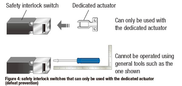
To prevent this type of safety interlock switch override, the switch is designed so that it cannot be defeated by items shown in figure 4 (other than the dedicated actuator). These include screws, needles, metal plates, screwdrivers and other tools, and common objects such as keys or coins.
In addition, there are other things to consider when mounting the safety interlock switch body and the dedicated actuator to the machine to prevent defeat.
The requirements for safety interlock switch defeat protection are detailed in the ISO 14119 international safety standard (Safety of machinery – Interlocking devices associated with guards – Principles for design and selection).
Read our explanation of the ISO 14119 safety standard to learn more:
Direct opening action
To ensure the safety of workers and maintenance personnel accessing the inside of the machine, when the door is opened the NC contact inside the safety interlock switch must be opened. This breaks the circuit and stops the machine.
For this reason, the NC contact within the safety interlock switch must have a direct opening action.
The direct opening action means that the actuator and NC contact are connected using only inelastic material. This allows the force used to open the door to be directly transmitted as force to the NC contact to open it.
As a result, opening the door opens all NC contacts, including any welded* NC contacts with direct opening action. This enables the machine to be stopped. (* a state where the surface of the contact melts, cools and then sticks together, e.g. due to an inrush current exceeding capacity during contact opening/closing)
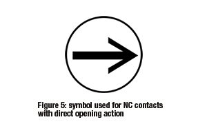
The arrow symbol shown in figure 5 represents NC contacts with the direct opening action feature.
Model selection based on whether door locking is required
There are two main types of safety interlock switches: non-locking, and locking. There are also two types of locking switches: those made for safety-related purposes (spring lock) and those made for non-safety-related purposes (solenoid lock).
Figure 6 shows 3 options for which of these types of safety interlock switch to select.There are two main types of safety interlock switches: non-locking, and locking. There are also two types of locking switches: those made for safety-related purposes (spring lock) and those made for non-safety-related purposes (solenoid lock).
Figure 6 shows 3 options for which of these types of safety interlock switch to select.
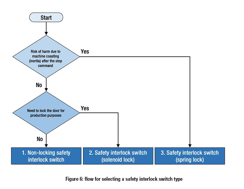
Option 1: if the hazardous moving parts of the machine will stop immediately on opening the door, and the door does not need to be locked, select a non-locking safety interlock switch.
Option 2: if the hazardous moving parts of the machine will stop immediately on opening the door, but the door must be locked for production purposes, etc., select a safety interlock switch with a solenoid lock (non-safety-related purposes).
Safety interlock switch (spring lock) applications
Figure 7 shows an example of a safety interlock switch (spring lock) mounted on the door of a machine tool.
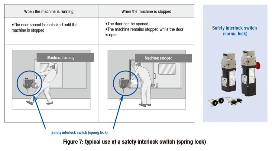
This type of safety interlock switch is mainly installed on machines with a large amount of inertia and that cannot be stopped immediately. The door remains securely locked while the machine is running, and can only be opened after coasting has completely stopped. This prevents harm to humans while the machine is coasting.
Safety interlock switches with spring locks are typically used with machines that have a high risk of mechanical hazards. These include large machining centers and lathes that keep coasting after a stop signal is received, and industrial robots that keep moving until the end of their task cycle.
As well as providing protection against mechanical hazards, these switches are used for isolation from hazards where it takes time for the risk level to subside, such as thermal hazards.
Safety interlock switch (spring lock) safety features
Figure 8 shows the basic method for locking and unlocking a safety interlock switch with a spring lock.
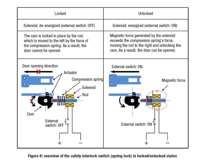
When the door is closed and the actuator is inserted, force from the compression spring moves the rod to the left. The rod is then locked in the cam. This is demonstrated in the diagram on the left side in figure 8.
In this state, the rod prevents the cam from rotating, so the actuator cannot be pulled out and the door is locked.
To unlock it, a current is applied to the solenoid to generate magnetic force.
When the force generated exceeds the compression spring’s force, the rod moves to the right and the lock is released, enabling rotation of the cam. This is demonstrated in the diagram on the right side in figure 8.
There are safety reasons for using this type of locking/unlocking mechanism. This is because the mechanism takes the possibility of unexpected power outages and disconnected cables into account.
If the lock were to be released due to an unexpected power outage or a cable disconnection, the machine would have too much inertia to come to an immediate stop. A worker could get caught up in this inertia, resulting in an accident.
When a safety interlock switch with a spring lock is used, power cannot be supplied to the solenoid when an unexpected power outage or cable disconnection occurs. As a result, the solenoid cannot be unlocked and the door cannot be opened. This means that an accident cannot be caused by a worker getting caught in a coasting machine’s inertia.
For machines with a high risk level due to their inertia, a safety interlock switch with a spring lock must be used to ensure safety in dangerous situations.
Safety interlock switch (spring lock) design
Figure 9 shows the standard configuration for a safety interlock switch with a spring lock.
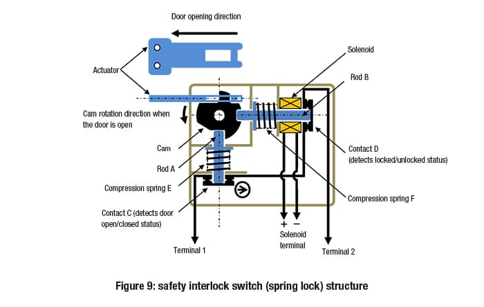
The left-hand side is almost identical to that of a non-locking safety interlock switch. When the door is opened or closed, the cam connected to the door-mounted actuator rotates to open or close contact C (used to detect whether the door is open or closed). This action either opens or closes the circuit between terminal 1 and terminal 2.
The right-hand side of the switch is the part that controls door locking and unlocking. Figure 9 shows the solenoid in a de-energized state (no voltage applied), and with rod B locked into the end of the cam by compression spring F. In this configuration, the door is locked.
As shown, in order to operate the machine the door must be not just closed, but locked. By connecting contacts C and D in series, the machine can be operated only when both are in the ‘on’ position.
Safety interlock switch (spring lock) and door opening/closing
Figure 10 shows the connection between a safety interlock switch with a spring lock and a door’s open/closed status.
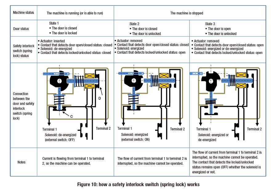
State 1
The door is closed and locked, and the machine is operational.
Looking more closely at the diagram, the actuator is inserted into the body of the switch. This means that contact C (NC) is closed.
In addition, the solenoid is not energized, and the rod is locked into the end of the cam by the force of the compression spring. Contact D (NC) is also closed.
As a result, the current flows from terminal 1 to terminal 2. This means that the door is closed and locked, and that the machine can be operated (in a safe state).
State 2
The machine has stopped, and the door is unlocked.
After separate detection that the machine has finished coasting and stopped, the solenoid is energized and contact D (NC) is opened.
As a result, the flow of current from terminal 1 to terminal 2 is interrupted, and the machine cannot be operated. As the solenoid has been energized, the door is unlocked and can be opened.
State 3
The door is open.
The actuator has been removed, and so the cam and rod have moved to open contact C (NC).
The cam’s rotation holds the rod in contact D (NC)’s open position, whether the solenoid is energized or not. In this way, when the door is open both contact C (NC) and contact D (NC) are open, reliably maintaining the stopped state of the machine.
To restart the machine, the door is closed to return it to state 1. However, with some exceptions, simply closing the door may cause the machine to start running, leading to unexpected accidents. Therefore, the operator must only be able to restart the machine by pressing a separate start button from a safe position, after checking that the surrounding area is safe.
Safety interlock switch (solenoid lock) applications
Figure 11 shows an example of a safety interlock switch (solenoid lock) mounted on a machine tool door.
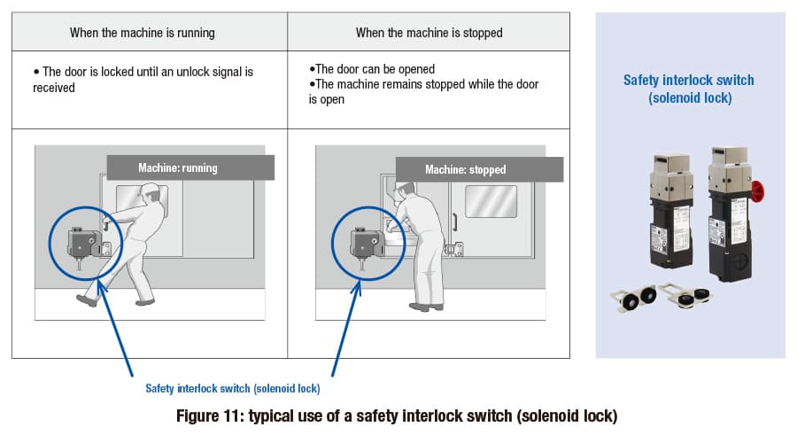
The door must be closed while the machine is running, to keep humans isolated from potential hazards. If the machine stops immediately when the door is opened, then the door does not need to be locked for safety reasons.
However, even if it is safe to open the door, it may need to be locked for production purposes or other reasons. These may include not wanting to stop the production line unnecessarily, or trying to avoid damaging and discarding workpieces.
Safety interlock switch (solenoid lock) safety features
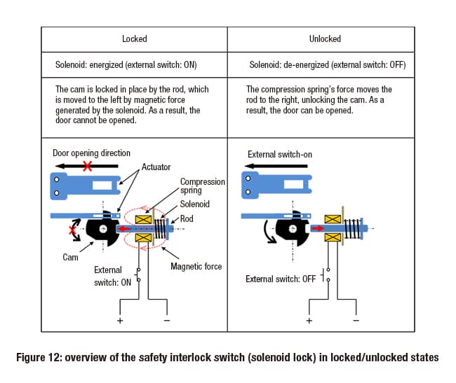
Figure 12 shows the basic method for locking and unlocking a safety interlock switch with a solenoid lock.
To lock the door, power is supplied to the solenoid after the door has been closed and the actuator has been inserted. The electromagnetic force exceeds the force of the compression spring, causing the rod to lock into the end of the cam.
When the power supply is cut off, the compression spring’s force moves the rod away from the cam (as shown on the right of the diagram), and the door is unlocked.
If there is an unexpected power outage or cable disconnection while the door is closed and locked, the lock will be released when power to the solenoid is cut off, and the door can be opened.
This means that mistakenly using a safety interlock switch with a solenoid lock on a machine with coasting inertia is extremely dangerous. If an operator opened the door to check the internal state of the machine during a power outage or while cables were disconnected, an accident could happen while the machine was still coasting.
As a result, safety interlock switches with a solenoid lock can only be used with machines that stop immediately when a stop signal is received, without coasting.
Safety interlock switch (solenoid lock) and door opening/closing
Figure 13 shows the correlation between a safety interlock switch with a solenoid lock and a door’s open/closed status.
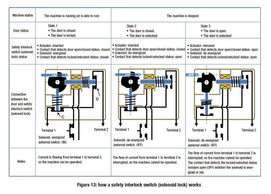
State 1
The door is closed and locked, and the machine is operational.
Looking more closely at the diagram, the actuator is inserted into the body of the switch. This means that contact C (NC) is closed. In addition, the solenoid is energized, and the rod is locked into the end of the cam by the force of the compression spring. Contact D (NC) is closed.
As a result, the current flows from terminal 1 to terminal 2. This means that the door is closed and locked, and that the machine can be operated (in a safe state).
State 2
The solenoid is de-energized, releasing the rod from the end of the cam. The cam can then rotate.
In this state, contact D (NC) is open. As a result, the flow of current from terminal 1 to terminal 2 is interrupted, and the machine cannot be operated. The door is unlocked, and can be opened.
State 3
The door is open.
The actuator has been removed, and contact C (NC) has been opened.
The cam’s rotation holds the rod in contact D (NC)’s open position, whether the solenoid is energized or not. In this way, when the door is open both contact C (NC) and contact D (NC) are open, reliably maintaining the stopped state of the machine.
To restart the machine, the solenoid must be energized after the door is closed, locking the door and returning it to state 1.
Precautions when installing safety interlock switches
There are several considerations when installing a safety interlock switch (non-locking, solenoid lock, or spring lock) on a machine.
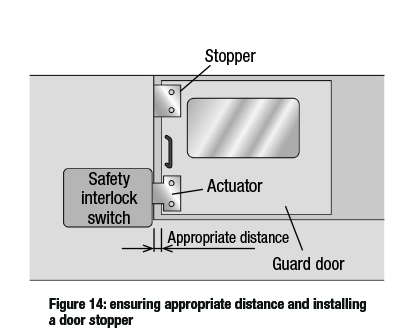
For example, there should be an appropriate amount of distance between the actuator and the switch body when the door is closed. Alternatively, a stopper should be mounted on the door (see figure 14). This will prevent the actuator or the door itself from colliding with the safety interlock switch body. A collision could cause the mounting position to shift, or damage the switch.
It is also important to be aware that the door may bounce back as a result of recoil when it is closed with force.
This is because the door bouncing back could lead to the following situations:
With non-locking safety interlock switches, when the door bounces back force is partially applied to the switch’s internal cam, causing only one of the dual NC contacts to open. This would be incorrectly recognized as an equipment failure, and the machine would not run.
With locking safety interlock switches, when the door bounces back force is applied to the locking mechanism. Movement of the rod generates friction, eventually meaning that the rod will not move even when trying to release the lock, and the door cannot be opened.
With locking safety interlock switches, when the door bounces back repeatedly force is applied to the locking mechanism multiple times. This could damage the locking mechanism and/or the NC contact opening/closing mechanism.
Conditions under which the machine is allowed to run
For the machine to run, two conditions must be satisfied: the door must be both closed and locked. For example, as shown in figure 9, these conditions can be satisfied by connecting the contact that detects door opening/closing and the contact that detects locking/unlocking in series.
This method is widely considered adequate from a safety standpoint, but requires two NC contacts (one to detect door opening/closing, and one to detect locking/unlocking).
On the other hand, some products are designed with an NC contact built into the safety interlock switch itself. These only allow the machine to run when the door is closed and locked.
In this case, only one NC contact is needed and the safety interlock switch can be smaller. Fewer contacts mean the size and cost of the switch can be reduced.
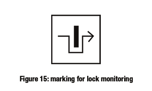
NC contacts that only allow the machine to run when the door is closed and locked are indicated by a marking for lock monitoring (as shown in figure 15). NC contacts with this symbol can be used in the safety-related part of a control system, serving as one of the safety conditions for machine operation.
However, in order to use an NC contact with the marking for lock monitoring as the sole safety condition, there is one more consideration.
That is: what happens when the locking mechanism breaks?
The locking mechanism may be damaged in the following cases:
if static force is applied to a locked safety interlock switch at a level exceeding the actuator pull-out strength when locked, as specified by the manufacturer, or
if dynamic force is repeatedly applied to the locking mechanisms due to recoil (bounce back) or other actions, even if the force is less than the actuator pull-out strength when locked.
All of this means that the failure state – whether the machine will stop (safe failure) or not (dangerous failure) if the locking mechanism breaks and the door opens – is an extremely important safety issue.
This is because safety interlock switches with the marking for lock monitoring are primarily used on machinery with a high risk of the operator suffering a serious accident. Even if the locking mechanism is damaged, the machine must be stopped to prevent such an accident.
As such, when selecting a safety interlock switch with a spring lock, we recommend choosing a product with the marking for lock monitoring (as shown in figure 15) and confirming the failure status in the event that the locking mechanism is damaged.
If the safety interlock switch (spring lock) locking mechanism is damaged resulting in a dangerous failure (the machine does not stop), or if it is uncertain whether a dangerous failure or a safe failure will occur, a door with a non-locking safety interlock switch or a safety limit switch must be installed separately from the safety interlock switch with a spring lock.
In cases where the necessary safety level is PLe, Category 4, the safety standard also requires installation of a door with a non-locking safety interlock switch or safety limit switch separately to the locking safety interlock switch.
IDEC safety interlock switches
We provide a wide range of help and resources:
If you have questions or suggestions, we're here to listen.
Our sales and support teams are on hand to help.
All the technical documentation you need.